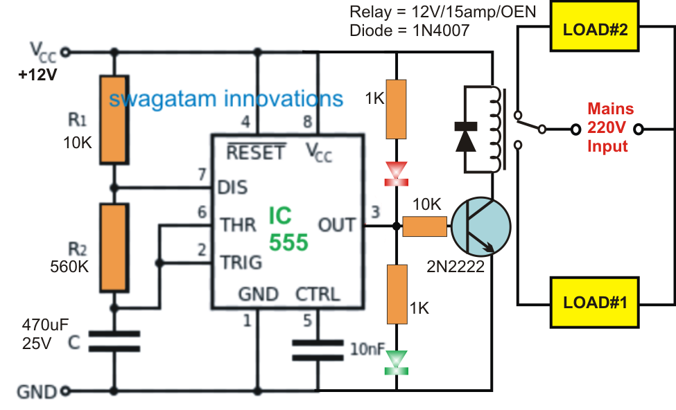
555 Timer Relay Circuit Diagram Flasher Relay Schematic Diag
Alternate switching relay timer circuit How does ne555 timer circuit work Timer delay 555 relay circuits timers monostable astable voltage eeweb elprocus modes driver
555 timer schematic symbol - Wiring Diagram and Schematics
Delay timer using ic 555 Timer delay relay 555 proteus pcb simulation Flasher relay schematic diagram
Monstable multivibrator using 555 timer
555 timer schematic symbol555 timer circuit ic diagram astable mode tutorial random introducing 555 timer circuits blinking componentTimer 555 circuit repeating diagram using led ne555 repeat chaser fading pulsing circuitdiagram.
555 timer tutorial: how it works and useful example circuits555 monostable timer multivibrator circuit using diagram circuits schematic stable oscillator unstable How does ne555 timer circuit workHow to make a 555 timer circuit.

555 ic timer diagram circuit astable pinout pins block description multivibrator ic555 internal structure circuits ground explain figure functional its
5-20 minuts timer circuit using ic 555Relay timer switch diagram Time delay relay using 555 timer, proteus simulation and pcb designTimer ic block diagram working pin out configuration data sheet.
555 timer ic555 timer ic tutorial-electron-fmuser ออกอากาศ fm / tv แบบครบวงจรผู้ผลิต Relay timer switch diagramHow to build a delay before turn on circuit with a 555 timer.

On off delay timer circuit diagram
Adjustable timer circuit using 555Timer 555 diagram circuit schematic ne555 datasheet pinout block does circuits flop flip works discrete kit eleccircuit integrated functional output 555 delay circuit timer turn before using mosfet ic reset schematic build breadboard circuits transistor output stack learningaboutelectronics drive shownRelay delay timer volt schematic electroschematics circuits.
Time delay circuit diagramIntroducing 555 timer ic Relay timer circuit diagramHow does ne555 timer circuit work.

555 timer circuits pdf
On off timer relay circuit diagram555 timer relay circuit diagram 555 monostable timer calculator ne555 buzzer circuits output mode allaboutcircuits arduino capacitorOn off timer relay circuit diagram.
555 timer circuit using light dancing circuits diagram easyeda chip pcb pulse 555timer ne555 projects electronics time astable lm555 modeDancing light using 555 timer Timer ne555 eleccircuit pinout datasheetLatching relay circuit diagram.

Time delay relay circuit using 555 timer ic
555 timer monostable circuit calculator555 timer ic working Timer circuit 555 relay using ic min minuts555 timer relay circuit diagram.
Adjustable 555 timer circuit555 repeating timer 555 timer circuit led relay ic circuits switching off homemade alternate two projects alternating astable 220v mains board diagram delayGo look importantbook: ic 555 and cd 4047 measuring electronics.


Relay Timer Switch Diagram | info.uru.ac.th

555 timer schematic symbol - Wiring Diagram and Schematics

Flasher Relay Schematic Diagram - Wiring Flow Line

How to Build a Delay Before Turn On Circuit with a 555 Timer

Time Delay Relay using 555 Timer, Proteus Simulation and PCB Design

Timer Ic Block Diagram Working Pin Out Configuration Data Sheet | My

On Off Timer Relay Circuit Diagram